Guitar Tuner
What technical possibilities do we have to measure the frequency f of the signal generated by an e-guitar?
1. measure the period T which is 1/f
For a pure sinus this will be a perfect method, but our signal is not a sinus . And , and this is the main problem, it changes dramatically over the time.
Let’s see how we can measure the period. The simplest method is to measure the time between two zero crossings. A zero crossing of the signal can be very simple determined by using a comparator. We don’t need an analog digital converter. It is very simple, cheap , and there are almost no specific HW and computational power requirement toward the microprocessor.
We only need a counter feed by a clock of defined period T = 1/Fcounter . Start the counter at one zero crossing of the signal, which is determined by the output of the comparator, and stop it at the next one. The period is the value of the counter N multiplied by the period of the counter clock . T = N * Tcounter = N/Fcounter .
Please imagine and insert here the “Sounds good, doesn’t work – Trump Meme”. Everybody knows this meme so no need for me to insert it really.
Due to the fact that the signal is not a sinus, as we can see from the signal form , there are multiple crossing through zero during one period, and the number of crossings is varying in time. Look bellow at the signal for E4 measured at the beginning and toward the end of the vibration.
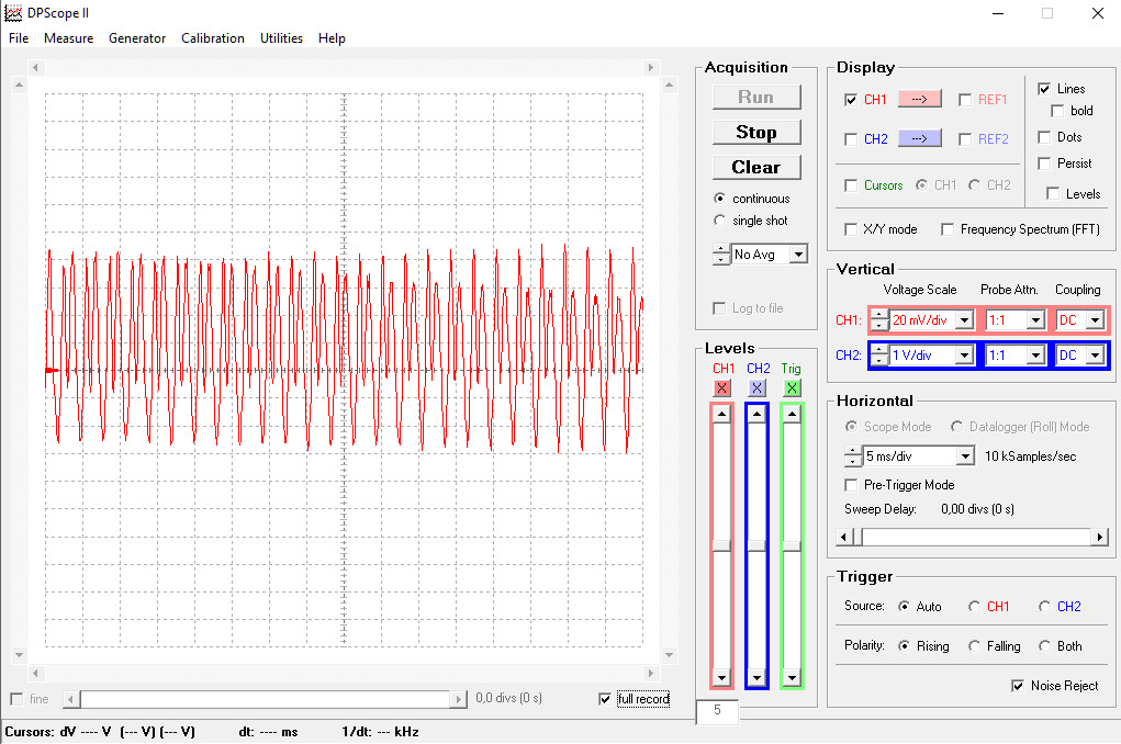
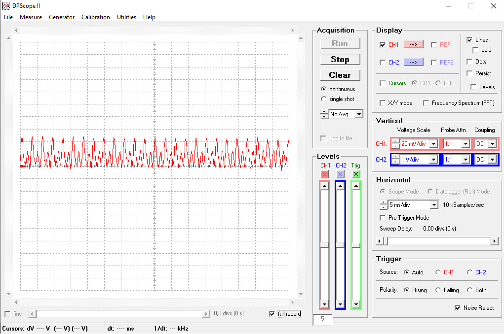
The two signals are completely different, although is the same chord. The reason is, as explained before, that over time the amplitudes of higher harmonics are decreasing faster than the fundamental, and the signal form varies corresponding. Measuring the duration between two consecutive zero crossing of this signals will give values different than the actual period of the fundamental and with large variations over time . Actually the method is not good for our purpose.

Anyhow , we can see from the signal form that the period is there. We may even guess the fundamental frequency. But this is only because we see the whole signal. So instead of looking for the zero cross, can we measure the period between two crossing of a different level? And at which level ? The amplitude is decreasing over the time , so any fix level we choose, except the zero one, will be sooner or later greater than the signal amplitude. In additional, as we see in the left picture, we may have two almost equal peaks in every period. We need to catch only one of them, for instance the highest. So the level must change over the time so that it catch the absolute maximum, and only this, at any given time. As the level is the compare value of a comparator, in order to make it variable over the time it has to be generated by a digital to analog converter, based on some algorithm . Or to use an analog to digital converter , instead of the comparator, and make the comparison in the software. But using a DAC or an ADC is not a very simple solution anymore and if we have anyhow to invest this amount of HW and SW effort then there are better ways to solve the problem.
Taking all of this in account we may say that measuring the period is theoretically possible, but only with a relative big effort, and since there are better solutions for the same effort, it is not practical.
2. Another possibility of measuring the frequency fundamental is the YIN algorithm.
You may find a detail description at this link.
Basically it works like this: We use an analog to digital converter and we sample the signal with a fix frequency. We sample for a time much longer than the duration of an estimates period and we will have M samples in total. We will have also N for each period of the signal but as we don’t know the period we don’t know N. Actually it is N we want to find. So we have a sequence of M values. We make a new sequence by moving each value from the initial sequence 1 step to the right and the most right one to the first place at the left. Now we extract each value of the new sequence from the value from the initial sequence situated on the same place in the sequence (first from first, second from second, …) . And we make a sum S1 by adding together all this differences. Then we make a new sequence by cyclically moving 2 steps and we calculate a new sum S2, and so on until we have M sequences, and M sums. When we generate all this sums at some point we will move with N moves. As the signal is periodic , and N is actually the period, the new sequence will be identical with the initial one and therefore each difference will be zero and the sum will also be zero. It is the same if we move with 2N steps and 3N steps and so on. We only need to look out for the first sums that is zero and we know the value of N. Now, in reality, as the sampling frequency is rarely an exact multiple of the signal frequency , the values of the samples from two consecutive periods are not equal, just very close, and the sum will not be zero but very low. Actually there will be two or three very low sums around the value corresponding to the signal period. let’s say at N-1 , N and at N +1. To determine the precise signal period we will have to interpolate between this three values, based on a second order formula. I don’t want to get any deeper in the mathematics. Not yet.
So we need to look for sum equal zero or, most frequent, for the minimums of the sum and do an interpolation between values. This algorithm require only simple operations and therefore almost no computational power.

What about the requirements on the hardware ? Let’s see what sample frequency fsample do we need. The highest note we want to measure is at least E4 which is 330Hz. Let’s round it to 350Hz. As the maximum allowed error is 0.15% we want to measure with a precision at least double. Let’s say 0.08%. For the highest frequency this is 0.08% * 350Hz = 0.28Hz. This is the lowest allowed precision . Highest is off course better. In order to achieve this precision after the interpolation, the difference between the frequencies corresponding to N-1, N, N+1, before the interpolation, should not be greater than let’s say 1-2Hz . Let’s take a maximum of 2Hz. Around 350Hz we should be able to determine for instance 348Hz, 350Hz, 352Hz and so on. In periods Tsampe this means that we should be able to determine the periods T348Hz = 1/348 = 2.874ms, T350Hz = 1/350 =2.857ms, T352Hz = 1/352 = 2.841ms. The difference between two consecutive periods (for instance between T350Hz and T352Hz is 2.857ms – 2.841ms = 0.016ms. Therefore the sampling frequency fsample should be higher than 1/0.016ms = 62.5kHz.
How about the resolution of the ADC? We want to have a precision of the measurement of maximum 0.15%. An ADC of 8 bits has 256 steps and therefore a maximal error of 100/255 = 0.4% . This is not good enough. We need to take an ADC with 10bits resolution. It will have 2↑10 = 1024 steps and therefore a maximal error of 100/1023 ≈ 0.01 % (actually a little bit less).
The internal ADC of the ATMega328 and ATMega32U4 used by the Arduino Mini, Micro and Nano is having a maximum sampling frequency of 77kHz, but only if using 8bit resolution. Using 10bit will decrease the maximum sampling frequency to 200kHz/13 ≈ 15kHz. Not good enough.
The conclusion is that if we want to use any of the Arduino Mini, Micro or Nano boards we have to use an external ADC. This will complicate a little bit the design and will increase slightly the price. Note: I only mentions this boards out of the Arduino family because those are in a small format, suitable for a pedal. Others are too big to fit inside a small pedal type case.
Not possible to use a simple Arduino together with the fact that the algorithm is patented made me to decide to rather not use it, even for my own development without any commercial interest.
3. The third possibility is by calculating the FFT of the signal and doing a frequency analysis.
We do this by calculating the complete frequency spectrum of the signal, using the Fast Fourier Transform (FFT) algorithm. The FFT is very useful for cases like ours. For those of you who don’t know (yet): the FFT is a mathematical algorithm which “transpose” the signal from amplitude vs. time in amplitude vs. frequency, therefore generating the frequency spectrum. Of course we are dealing with digital signals meaning discrete samples. The generated frequency spectrum will be a discrete one too. For a number N of samples we will get through “transposing” a number of N discrete frequency. Given the sampling frequency fsample this will be also the maximum frequency in the calculated discrete spectrum and the interval between each discrete frequency is fsample / N. Note that this are discrete frequency and in order to get the exact one we will have to interpolate between three adjacent values.
What are the requirements on N and fsample ?
First of all , as a certain Mr. Nyquist told us in his Criterion, the sampling frequency fsample has to be at least double the highest frequency to be sampled and/or measured. In our case double than the E4 chord frequency ≈ 2* 350Hz = 700Hz.
Second: the number of samples. Actually the algorithm is ideal only if the number of samples is infinite in both time directions. This is not good cause the universe is only 13.7 billion years old. For a finite number of samples there will be errors but this errors are negligible if the number of samples is high enough. On the other hand the FFT algorithm is taking longer to compute as the number of sample increase. We want to have only a reasonable amount of processor time dedicated to the FFT and to finish the FFT calculation before a new set of N samples are ready , otherwise the whole thing will be f****d up. Therefore we have to compromise between a lot of samples with high accuracy of the result and only a few but the processor doing his thing on time.
Third : the correct frequency will be for sure not exactly one discrete value , but somewhere between two discrete values. So, in order to get the correct value, we have to interpolate second order using three consecutive discrete values.

To determine the frequency, after the interpolation, with a precision of 0.08%, even for the worst case, which is the highest frequency (0.08%*350Hz = 0.28Hz), we must have a spacing of the discrete frequencies, before the interpolation, of max. 1-2Hz.
Now we have to do a compromise between all this . After all, that’s what engineering is all about. Finding the best compromise. So let’s assume a spacing between frequencies of 2Hz and a number of samples of 1024 (the FFT algorithm works best only if the number of samples is a power of 2). Then the maximum frequency in the spectrum will be 2*1024 = 2048Hz and this is also the sampling frequency. Going the other way round of Ms. Nyquist saying , the maximum signal that we can detect/measure, using 2048Hz as sampling frequency, will be 2048/2 = 1024Hz, which is actually the note B5, way above what the tuning of a guitar needs. So everything is fine.
Sampling 1024 samples, with a sampling frequency of 2048Hz, will take 1024/2048 = 0.5sec. So we will have a new FFT only each 0.5sec. We may calculate/display the real frequency only two times per second. It is not very fast. But faster will mean either less samples and this will imply less accuracy, which is not nice, or increasing the sampling frequency while keeping the same amount of samples, which will decrease the accuracy also. Well, I personally, I can live with two samples/sec. but having the accuracy I am aiming for. For me this seams to be a good compromise.
The requirements for the hardware are : ADC with 10bit and 2kHz sampling frequency. Piece of cake. But the processor must work at a high frequency cause the FFT algorithm needs quite some computation power.
Finally I settle for this project for the FFT method. And maybe I will try some other time, when I will be in the mood, the Yin method too. But for now:

To be continue with the hardware design.